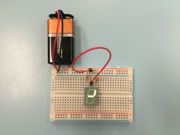
Seven segment displays are commonly used in many electrical applications, including alarm clocks, timers, and scales. In this tutorial, you will learn how to use your own 7-segment displays!
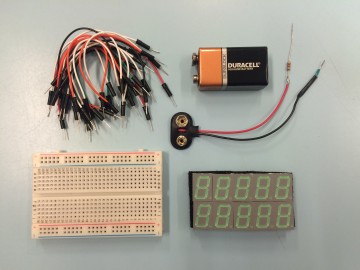
A 7-segment display is an electronic device that can be used for displaying numerals and some letters. Different letters/numbers can be represented by connecting different pins on the display to the battery, which turns on the LEDs in parallel. This activity introduces how to use a 7-segment display using only a battery, a breadboard, a resistor, and some wires.
LEDs are really fun to learn how to use – if you want to learn more about how the LEDs inside of a 7-segment display work, you can find more information at the bottom of this page.
Supplies
You can find most supplies from your local electronics stores or online.
- A breadboard. If you are not familiar with how a breadboard works, this is a useful introduction.
- Some jumper wires, such as these ones from Digikey (#377-2093-ND) that are easy to use with a breadboard.
- Some 7-segment displays. There are a few different pin configurations – we like these ones (#160-1575-5-ND) from DigiKey.
- 360+ ohm resistor(s). We used a 470 ohm resistor. Any resistor value between 360-500 ohms will work for this activity.
- A 9 V battery and a battery clip.
Safety
- Be careful not to let the wire leads from the battery touch each other. This will short the battery (the battery will heat up and could become dangerous).
- Adult supervision needed for soldering.
- Adult supervision should be used to look up the type of 7-segment display you are using on the internet. It is important to know whether the device is common anode (like the ones we are using) or common cathode. The maximum current rating and the connections inside different 7-segment displays may be different, and not using the devices correctly can “burn out” an LED (it is unlikely that the 7-segment will actually become hot, but the LED inside the segment can become unusable)
Instructions
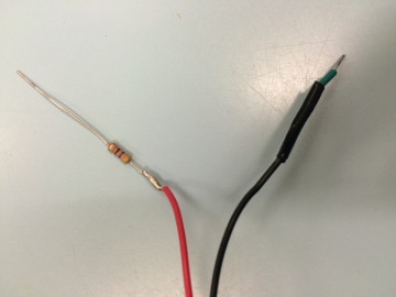
A note on resistors: The 360+ ohm resistor used in this activity is chosen to limit the supplied current from the battery to a maximum of 25 mA, which is the maximum current for the device we are using. There are multiple ways to ensure that the current won’t exceed the maximum for your device. The easiest way to do so, described in this section of the activity, is to solder a 360+ ohm resistor to the positive lead of the battery clip. This will ensure the maximum supplied current is 25 mA, but will decrease the brightness of the LEDs as you add more segments. An alternate configuration, using one 360+ ohm resistor for each segment lit up, requires more resistors but does not require soldering and will not result in the loss of segment brightness.
1. Solder a resistor to the positive lead of the battery clip. You can add electrical tape to the connection for stability.
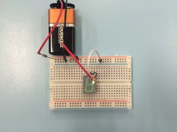
2. Attach the battery clip to the battery. Insert the positive (red) end of the battery clip into the ‘+’ rail of the breadboard, and the negative (black) end of the battery clip into the ‘-‘ rail.
3. Using a jumper wire, connect the ‘+’ rail with the common anode pin – this provides power to the device.
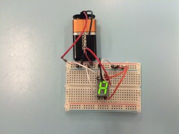
4. Using another jumper wire, connect the other pins to the ‘-‘ rail. The segment that is connected to this pin should now turn on!
5. Try connecting other pins with jumper wires to the ‘-‘ rail. How many segments can you light up? Can you make a number or letter?
6. Try connecting more 7-segment displays on the breadboard. Can you write the word ‘HI’? Can you write the word ‘HELLO’?
More About Diodes
The 7-segment display is a device made up of seven LEDs connected in parallel. LED is an acronym for Light Emitting Diode. LEDs work very similarly to normal diodes – except that when an LED is on, it emits light. Below is a typical pin configuration and block diagram for a common anode 7-segment display, like the one we used in this activity.
As you can see in the block diagram, a diode is shown as a triangle and a line. The direction in which the triangle is pointing changes how the diode works. If we were to connect the positive end of the battery to the line labelled ‘3,8’ and the negative end of the battery to the line labelled ‘7’, the LED ‘a’ would turn on. However, if we reversed the battery connections, nothing would turn on. Why? Because the diode would not be on!
To turn a diode on, you need to make sure current is flowing through the diode in the direction the triangle is pointing (called the forward direction). If current isn’t flowing, or is flowing in the opposite (reverse) direction of the triangle, the diode will be off. In this case, since the triangle of diode ‘a’ is pointing down, we can make the current flow down by connecting the positive end of the battery to ‘3,8’ and the negative end of the battery to ‘7’.
Alternate Configurations
By following the instructions above, you will be able to successfully light 3-4 7-segment displays without significant brightness loss. However, connecting more segments will reduce the current flowing through the LEDs until the segments will barely light up. Using one 360 ohm resistor for every connected segment will ensure that all segments are supplied by approximately 25 mA. This configuration is shown below.
